Momentary Pulse Relay Circuit Diagram
Special applications with spdt relays Relay schematic keep state circuit circuitlab created using electronics Handling high pulse current through relay contacts
Relay circuits Instrumentation Tools
Dpdt momentary switch wiring diagram / switch wiring diagrams Single momentary pulse to toggle on/off Relays relay negative momentary output wiring off diagram positive the12volt latched using immobilizer locking remote kit pulses two wire
Relay pulse current circuit contacts through using schematic handling high circuitlab created
Momentary_relay_circuitHow to understand basic circuit theory? designing basic electronic Pulse button power keep circuit load using schematic pressed until turn circuitlab created stackRelay momentary circuit electronic activation.
Relay latching switch momentary circuit teamed circuits diagram schematic push next button coil spst grLatching relay source Czh pulse relay momentary14+ latching relay wiring diagram.

Latched on/off output using two momentary positive pulses
Basic circuitRelay 24v isolated schematic circuit controller control circuits relays gr next current board Pulse relayHow to design a voltage stabilizer using relays and lm324 op-amp and.
Circuit schematic voltages supply minutes every different circuitlab created using relayMomentary dpdt relay latching latch littelfuse humbuckers pickup neg Relay circuits instrumentation tools12v momentary constant button circuit sport output relay relays capacitor time power diagram delay windows gif the12volt applications special spdt.

Flop flip circuit relay latching relays plc logic using toggle wiring switch pulse creating source wired example ladder remote installbay
Relay circuitsMomentary relay latching toggle pulse single off circuit schematic asked mechanical electronics supply local would work house Latched on/off output using two momentary negative pulsesIsolated 24v relay controller.
Circuit electronic basic theory circuits time pulse capacitor understand designing used easy made understanding indicating delays producingCircuit function multi relay adjustable general time seekic Relay pulse circuit seekic basic diagram buttonRelay circuit switch circuits contact control state schematic pressure diagram coil sends insufficient actuate remains closed normal since its instrumentationtools.

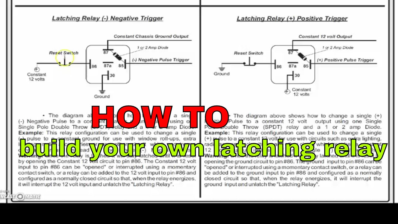
Relay off pulse diagram negative positive momentary single using latching wiring output latched neg if
Pulse button power schematic keep turn using relay circuit pressed load until switches electronics circuitlab created stackMomentary switch teamed with latching relay Circuit momentary relay seekic controlLatched on/off output using a single momentary positive pulse.
Wiring understandRelay output relays 12v momentary latching diagram constant wire using button wiring input control power spdt switch circuit the12volt latch Electronic design blog: relay circuitsRelay latching wiring momentary output latched convert.

Relay output positive relays wiring diagram momentary two diode using ground off diagrams latched pulses coil
Multi-function adjustable general time relay circuitRelay latching self normally open contacts dpdt 12v pulse input dpst switches way two could also stack Lm324 relay stabilizer relays ne555 voltage timerCzh-labs panel mount momentary-switch/pulse-signal control latching.
Relay wiring diagram and function explainedRelay control circuit circuits switch light pressure activates alarm where contact instrumentationtools .


Electronic Design Blog: Relay Circuits

Relay Wiring Diagram and Function Explained - ETechnoG

Basic circuit - 12v trigger to momentary relay? | Overclockers UK Forums

How to design a voltage stabilizer using Relays and LM324 Op-Amp and
14+ Latching Relay Wiring Diagram | Robhosking Diagram

Multi-function adjustable general time relay circuit - Control_Circuit

Relay circuits Instrumentation Tools